Computer Networks (Information Technology)
- Data Communication and Networking


The Tech Trailblazer
Hello All, Join the journey of Harshi (let's learn and grow together) !!!
Before becoming a Data Scientist did you ever think of having a 360 degree overview of some most important fields such as Information Technology, Computer Science, Business Knowledge etc. Which helps you to understand and have a deep idea about the industry you work at. You might be from different backgrounds(fields) before becoming a data scientist but don't worry, being human no one will force you or expect you to have knowledge of all the subjects but at least having knowledge of IT(Information Technology), Computer Science and Data Science and AI will help you to stand apart from the crowd, more over you will be having confidence in dealing with real time problems when you work for companies.
Elevating IT's echo -
Information Technology (IT) refers to the use, development, and management of computer systems, software, networks, and electronic infrastructure to store, process, transmit, and retrieve information. IT plays a crucial role in various aspects of modern life, impacting businesses, education, healthcare, communication, entertainment, and more. Here are key components and aspects of Information Technology:
Hardware: This includes physical devices such as computers, servers, networking equipment, storage devices, and peripherals. Hardware components form the foundation of IT systems.
Software: Software encompasses applications, operating systems, and other programs that enable users to perform specific tasks on computers and devices. It includes both off-the-shelf applications and custom-developed software.
Networks: IT relies heavily on networks to facilitate communication and the sharing of information.
Local Area Networks (LANs), Wide Area Networks (WANs), and the internet are critical components of network infrastructure.
Data Management: IT involves the collection, storage, retrieval, and manipulation of data. Database management systems (DBMS) are used to organize and manage large volumes of data efficiently.
Cybersecurity: IT security is crucial to protect systems, networks, and data from unauthorized access, cyberattacks, and data breaches. This includes the implementation of firewalls, antivirus software, encryption, and other security measures.
Cloud Computing: Cloud computing involves the delivery of computing services, including storage, processing power, and applications, over the internet. It allows organizations to access resources without the need for physical infrastructure.
Information Systems: Information systems combine hardware, software, data, and processes to support organizational activities. Enterprise Resource Planning (ERP), Customer Relationship Management (CRM), and other systems help manage business operations.
Web Technologies: Web development, HTML, CSS, JavaScript, and other web technologies are integral to creating websites and web applications, enabling online communication and collaboration.
Emerging Technologies: IT is continually evolving with the introduction of emerging technologies such as artificial intelligence, machine learning, blockchain, the Internet of Things (IoT), and augmented reality.
IT Management: IT departments within organizations are responsible for planning, implementing, and maintaining IT infrastructure. IT managers oversee projects, budgets, and ensure that technology aligns with business goals.
End-User Support: IT professionals provide technical support to end-users, troubleshooting issues, and ensuring that systems and applications are functioning correctly.
The field of Information Technology is diverse, encompassing a wide range of disciplines and specialties. Professionals in IT contribute to the development and maintenance of technology infrastructure, the creation of software solutions, and the implementation of strategies to leverage technology for business and societal advancement.
What actually is a computer network?
A computer network is a set of interconnected computers that communicate with each other to share resources and information. Networks can be as small as two computers connected in a home or as large as a global network that spans the entire planet. The primary purpose of a computer network is to enable the sharing of resources and information among interconnected devices. Here are some key concepts related to computer networks:
Nodes: Nodes are the individual devices (such as computers, printers, servers, etc.) that are part of the network. Each node has a unique identifier, commonly known as an IP address, which is used to facilitate communication.
Links: Links are the physical or wireless connections that enable communication between nodes. They can include wired connections like Ethernet cables or wireless connections like Wi-Fi.
Ethernet cables are a type of networking cable commonly used to connect devices in a local area network (LAN) and to provide wired internet access. They are part of the Ethernet standard, which defines the protocols for the networking technologies used in most wired LANs.
Key characteristics of Ethernet cables include:
Physical Construction: Ethernet cables typically consist of four twisted pairs of copper wires, although variations with more pairs exist. The twisting helps reduce electromagnetic interference from other cables and electronic devices.
Categories (Cat): Ethernet cables come in different categories, such as Cat5e, Cat6, Cat6a, Cat7, and Cat8. Each category has specific specifications for performance, such as data transfer speed and maximum cable length. Newer categories generally support higher data rates and better shielding.
RJ-45 Connectors: Ethernet cables use RJ-45 connectors, which look similar to, but larger than, the RJ-11 connectors used for telephone cables. The RJ-45 connector has eight pins, corresponding to the eight wires in the cable.
Usage: Ethernet cables are commonly used to connect devices such as computers, printers, routers, switches, and other networked devices. They are also used to establish a wired connection between a modem and a router to provide internet access to devices in a home or office.
Twisted Pair Configuration: The twisted pair configuration helps reduce crosstalk and electromagnetic interference, improving the reliability and performance of the cable.
Color Coding: The individual wires within an Ethernet cable are color-coded to facilitate proper termination of the cable. The most common color-coding scheme is the T568B standard, where the wires are arranged in a specific order: white with blue stripes, blue, white with orange stripes, orange, white with green stripes, green, white with brown stripes, and brown.
Cross-over Cables: In addition to regular straight-through cables, there are also crossover cables. Crossover cables are used to connect two similar devices directly, like connecting two computers without the need for a switch or router.
Shielding: Some Ethernet cables, especially those in higher categories like Cat7 and Cat8, have additional shielding to reduce interference further and support higher data rates over longer distances.
Ethernet cables provide a reliable and stable means of establishing wired connections in a network, offering advantages such as low latency and resistance to interference compared to wireless connections. The choice of cable category depends on the specific requirements of the network in terms of speed, distance, and environmental conditions.
Topology: Network topology refers to the physical or logical layout of the network. Common topologies include bus, star, ring, mesh, and hybrid configurations, each with its own advantages and disadvantages.
Protocols: Network protocols are sets of rules and conventions that govern how data is transmitted and received in a network. Examples include TCP/IP (Transmission Control Protocol/Internet Protocol), which is the foundation of the Internet.
LAN (Local Area Network) and WAN (Wide Area Network): LANs are networks that are limited to a small geographic area, such as a single building or a campus. WANs, on the other hand, cover larger geographic areas and may span cities, countries, or even continents.
Internet: The Internet is a global network of interconnected networks. It allows for worldwide communication and access to a vast amount of information and resources.
Routers and Switches: Routers connect different networks and facilitate data traffic between them. Switches are devices that operate at the data link layer and are used to connect multiple devices within the same network.
Firewalls: Firewalls are security devices that control and monitor incoming and outgoing network traffic based on predetermined security rules. They help protect networks from unauthorized access and potential cyber threats.
Wireless Networks: Wireless networks use radio waves or infrared signals for communication instead of physical cables. Wi-Fi is a common example of a wireless network technology.
Intranet and Extranet: An intranet is a private network within an organization, while an extranet is a network that allows controlled access from outside the organization, often for business partners or customers.
Computer networks play a crucial role in modern communication and are integral to various applications, including email, web browsing, file sharing, and collaborative work environments.
LET'S DIVE INTO SOME IMPORTANT COMPONENTS OF THE COMPUTER NETWORK
- A Network Interface Card (NIC) is a hardware component that allows computers to connect to a network. It is also sometimes referred to as a network adapter or LAN adapter. The NIC is responsible for the physical connection between the computer and the network, facilitating communication by converting data between the computer's internal data bus and the network's communication medium, which can be wired (e.g., Ethernet) or wireless (e.g., Wi-Fi).
Here are key points about Network Interface Cards:
Physical Connection: NICs can be integrated into the motherboard of a computer or added as a separate expansion card. In the case of laptops and some modern desktops, NICs may be integrated directly into the system.
Media Type: NICs are designed to work with specific network media types. For example, an Ethernet NIC is designed for wired Ethernet connections, while a Wi-Fi NIC is designed for wireless connections.
Data Link Layer: NICs operate at the Data Link Layer (Layer 2) of the OSI model. They are responsible for framing data into packets, adding addressing information (such as MAC addresses), and handling error detection.
MAC Address: Each NIC has a unique Media Access Control (MAC) address, which is a hardware address burned into the NIC's firmware. The MAC address is used to identify devices on a network.
Drivers: To enable communication between the operating system and the NIC, the computer requires a device driver. The driver is a software component that facilitates communication and ensures that the NIC operates correctly with the operating system.
Speed and Standards: NICs come in various speeds and standards, such as 10/100/1000 Mbps (Ethernet) or various Wi-Fi standards (e.g., 802.11ac). The speed of the NIC determines how quickly data can be transmitted and received on the network.
Half-Duplex and Full-Duplex: NICs can operate in half-duplex or full-duplex mode. In half-duplex, data can be transmitted or received, but not both simultaneously. In full-duplex, data can be transmitted and received simultaneously, improving overall network efficiency.
Auto-Negotiation: Many modern NICs support auto-negotiation, allowing them to automatically determine the best possible speed and duplex mode for communication with the connected network device.
NICs play a crucial role in enabling computers to participate in local area networks (LANs) or connect to the internet. They are a fundamental component for wired and wireless network connectivity in both home and business environments.
Hub:
Function: A hub operates at the physical layer (Layer 1) of the OSI model. It simply connects multiple devices in a network, and when one device sends data, the hub broadcasts that data to all other devices on the network.
Intelligence: Hubs are considered "dumb" or "unintelligent" devices because they do not analyze data and do not have the ability to selectively forward data to specific devices. All connected devices share the available bandwidth.
Efficiency: Hubs can lead to network congestion and collisions, as all devices share the same communication medium.
Router:
Function: A router operates at the network layer (Layer 3) of the OSI model. Its primary function is to connect different networks and route data between them. Routers use logical addressing (such as IP addresses) to determine the best path for data to travel between networks.
Intelligence: Routers are intelligent devices that make decisions based on destination IP addresses. They can filter and forward data selectively, making them more efficient in managing network traffic.
Network Segmentation: Routers help segment networks, providing isolation between different parts of a network. This can enhance security and optimize network performance.
Switch:
Function: A switch operates at the data link layer (Layer 2) of the OSI model. It connects devices within the same local network and selectively forwards data to the specific device for which it is intended.
Intelligence: Switches are more intelligent than hubs. They use MAC addresses to make forwarding decisions, reducing unnecessary network traffic and collisions. Each port on a switch represents a separate collision domain, improving network efficiency.
Efficiency: Switches provide dedicated bandwidth to each connected device, avoiding the congestion issues associated with hubs. They improve network performance by reducing collisions and allowing for full-duplex communication.
In summary:
Hub: Basic, operates at Layer 1, broadcasts data to all devices.
Router: Connects different networks, operates at Layer 3, uses logical addressing, and selectively routes data based on IP addresses.
Switch: Connects devices within the same network, operates at Layer 2, uses MAC addresses for selective data forwarding, and provides dedicated bandwidth for each connection.
In modern networks, switches and routers are more commonly used than hubs, as they offer better performance, security, and flexibility.
Cables and Connectors: In computer networks, various cables and connectors are used to establish connections between devices and facilitate the transmission of data. The selection of cables and connectors depends on factors such as the type of network, data transfer speed requirements, and the distance between devices. Here are some common cables and connectors used in computer networks:
Ethernet Cables:
Description: Ethernet cables are widely used in local area networks (LANs) to connect devices such as computers, printers, switches, and routers.
Types: Cat5e, Cat6, Cat6a, Cat7, Cat8.
Connectors: RJ-45 connectors are commonly used with Ethernet cables.
Use: Wired network connectivity for data transfer and communication.
Fiber Optic Cables:
Description: Fiber optic cables use light signals to transmit data, providing high-speed and long-distance communication.
Types: Single-mode fiber (SMF), multimode fiber (MMF).
Connectors: LC, SC, ST, MTP/MPO.
Use: High-speed data transmission over long distances in networks.
Coaxial Cables:
Description: Coaxial cables are used for transmitting data signals, especially in cable television (CATV) networks.
Types: RG-6, RG-58.
Connectors: F-type connectors.
Use: Cable television, internet connections, and some network connections.
USB Cables:
Description: USB cables are commonly used for connecting various peripheral devices to computers, including printers, external hard drives, and more.
Types: USB-A, USB-B, USB-C.
Connectors: USB connectors are standardized and match the type of USB port on the devices.
Use: Peripheral connectivity and data transfer.
Serial Cables:
Description: Serial cables are used for serial communication between devices, often in console connections to network equipment.
Types: RS-232, RS-422, RS-485.
Connectors: DB-9, DB-25.
Use: Console connections to routers, switches, and other network devices.
Power over Ethernet (PoE) Cables:
Description: PoE cables carry both data and electrical power, allowing devices like IP cameras and VoIP phones to receive power over the same Ethernet cable used for data transmission.
Use: Powering and connecting network devices.
Crossover Cables:
Description: Crossover cables are used to connect similar devices directly, such as connecting two computers without the need for a switch.
Connectors: Typically use RJ-45 connectors.
Use: Direct device-to-device connections without an intermediary network device.
Modular Connectors:
Description: Modular connectors are commonly used in telecommunications and networking for various applications, including telephone connections and Ethernet.
Types: RJ-11, RJ-45.
Use: Telephone connections, Ethernet networking.
The selection of cables and connectors in a network depends on the network's design, requirements, and the types of devices being connected. The proper installation and use of these cables and connectors are essential for maintaining a reliable and efficient network.
Modem:
A modem, short for "modulator-demodulator," is a device used in computer networks to modulate and demodulate signals for the purpose of transmitting data over communication channels. Modems are crucial for enabling communication between digital devices, such as computers, and analog communication systems, like telephone lines or cable systems.
Here's a basic overview of how modems work and their role in computer networks:
Modulation:
Transmission of Digital Data: Digital devices, like computers, generate and process digital data in the form of binary signals (0s and 1s).
Modulation: Modems convert these digital signals into analog signals suitable for transmission over analog communication channels.
Demodulation:
Reception of Analog Signals: Analog communication channels transmit signals in the form of varying voltage or frequency.
Demodulation: Modems at the receiving end demodulate the analog signals back into digital signals that computers and digital devices can understand.
Types of Modems:
Dial-Up Modems: Historically, dial-up modems were common for connecting to the internet over telephone lines. They operate at relatively lower speeds and are not widely used today due to the prevalence of broadband technologies.
DSL Modems: Digital Subscriber Line (DSL) modems use telephone lines but offer faster data rates than traditional dial-up modems.
Cable Modems: Cable modems use cable television infrastructure to provide high-speed internet access. They are commonly used in residential and business settings.
Fiber Optic Modems: These modems work with fiber optic communication systems, providing very high data transfer rates. Fiber optic modems are often used in advanced broadband networks.
Role in Computer Networks:
Modems are used to connect computers and other digital devices to the internet or other remote networks.
They facilitate the transmission of data over various communication channels, including telephone lines, cable systems, and fiber optic networks.
Modems play a role in both sending and receiving data, allowing for bidirectional communication.
Data Transfer Speeds:
- Modems are often rated based on their data transfer speeds, measured in bits per second (bps) or kilobits per second (Kbps). Higher-speed modems enable faster data transmission, which is crucial for activities like web browsing, streaming, and online gaming.
It's worth noting that with the widespread adoption of broadband technologies like DSL, cable, and fiber optics, traditional dial-up modems have become largely obsolete for high-speed internet access. However, modems, in various forms, continue to be an integral part of the network infrastructure, connecting users to the internet and facilitating data communication.
Computer networks serve a variety of purposes and have become an integral part of our daily lives. Here are some common uses of computer networks:
Internet Access:
- One of the primary uses of computer networks is to provide access to the internet. Users can browse websites, send emails, stream videos, and engage in online activities through network connectivity.
Communication:
- Computer networks facilitate communication by enabling the exchange of emails, instant messages, video calls, and voice calls. Social media platforms also rely on networks for users to connect and share information.
File Sharing:
- Networks allow users to share files and resources seamlessly. This includes sharing documents, images, videos, and other data between devices on the same network.
Remote Access:
- Networks enable remote access to files, applications, and systems. Users can access their work computers from home or connect to remote servers for data retrieval and processing.
Collaboration:
- Networks support collaborative work environments. Multiple users can work on the same document simultaneously, and teams can collaborate on projects in real-time using networked tools and platforms.
Online Gaming:
- Multiplayer online games rely on computer networks to connect players worldwide. Gamers can compete or cooperate with each other in real-time, enhancing the gaming experience.
E-commerce:
- Computer networks are essential for e-commerce platforms, enabling online shopping, payment transactions, and secure financial transactions over the internet.
Data Storage and Backup:
- Network-attached storage (NAS) and cloud storage services leverage computer networks to provide centralized data storage and backup solutions. Users can access their files from different devices.
Information Sharing:
- Networks facilitate the sharing of information within organizations, allowing employees to access databases, intranets, and other information repositories.
Educational Resources:
- Educational institutions use networks to provide online courses, access educational resources, and facilitate communication between students and teachers.
Telecommuting:
- With the rise of remote work, computer networks play a crucial role in telecommuting. Employees can connect to their company's network from home, accessing files and applications necessary for their work.
Entertainment Streaming:
- Networks support the streaming of music, movies, TV shows, and other forms of entertainment. Services like Netflix, Spotify, and YouTube rely on network connectivity for content delivery.
Smart Devices and IoT:
- The Internet of Things (IoT) involves connecting everyday devices to computer networks, enabling them to communicate and share data. Examples include smart thermostats, wearable devices, and home automation systems.
Research and Development:
- Researchers can collaborate globally, sharing data and findings through computer networks. High-performance computing clusters connected via networks are used for complex scientific computations.
These uses highlight the versatility and importance of computer networks in various aspects of modern life, from personal communication to business operations and beyond.
COMPUTER NETWORK ARCHITECHTURE :
There are two types of networks in the architecture:
Peer-to-Peer Architecture
Client/Server Architecture
Sever is responsible for "Security and Network management" and also it is responsible for managing all the resources such as file, directories, printers etc, all clients communicate with each other through servers. Backup of data is easy in client/server model.
- A server needs Network Operating Systems (NOS)to provide resources to the client, but the cost of NOS is very expensive.
Let's easily understand about Hub, Switch, Router...
Hub : Connects all the devices on the network. Hubs are present on layer1 called physical layer. Hubs are dumb unlike switches, that says hubs are unintelligent because they cannot filter the data or analyze the data and do not have the ability to selectively forward the data to specific devices. All the connected devices share the available bandwidth.
Router : It is operated at layer 3 called Network Layer of OSI model. It's main function is to connect all the Networks and route the data between them.
Routers use logical address(IP address) to determine the best path.
Switch: Switch operates at layer2 called Data link layer , it connects the devices same as hub but switch is an intelligent system , because it has the ability to filter and selectively forwards the data.
NOW LET'S SEE COMPUTER NETWORK TYPES
LAN
PAN
MAN
WAN
LAN (LOCAL AREA NETWORK) : within office environments, within campus or within a building.
PAN(PERSONAL AREA NETWORK): It is a network that is in the range of within 10 meters. Used for personal usage , covers an area of 30 feet.
Example: Mobile and Bluetooth headphones, computer and printer, play stations(X-Box).
There are 2 types of PANs
1. Wired PAN - used by using Wi-fi , Bluetooth
2. Wired PAN - used by using USB
**MAN( METROPOLITAN AREA NETWORK) -**Covers large geographic area by interconnecting different LAN's to form a large network. Govt. agencies use MAN to connect to the citizens and private industries.
In MAN, different LAN's are connected to each other through a telephone exchange lines. I
Example: MAN is used to connect different Bank Branches in a city.
It can also be used in airline bookings
It can also be used in Universities within a city.
It is also used in Communication in Military.
WAN (WIDE AREA NETWORK) - Extends over larger geographical area than MAN i.e. States and even Countries.
It uses telephone lines under water(Seas, oceans), fiberoptic cables or satellite links.
"INTERNET" is the biggest WAN in the world.
Example: Business, Govt, education etc. uses WAN.
INTERNETWORK
connection of 2 or more WAN's or LAN's or computer network segments together.
It uses IP (Internet Protocol) , protocol means set of rules
The reference model used for internetworking is OPEN SYSTEM INTERCONNECTION (OSI Model)
Types of Internetwork:
Extranet: Uses Internet protocol (IP protocol) especially TCP (Transmission control protocol).
- The access to the extranet is restricted only to the users who have login credentials.
Intranet: Intranet is accessible only by organization employees.
NETWORK TOPOLOGY
Topology is the structure(skeleton) of network of how all the components are connected in a network.
There are 2 types of Topology divisions:
Physical Topology
Logical Topology
Physical and logical topologies refer to different aspects of how computer networks are structured. Let's break down the key differences between them:
Physical Topology:
Definition: Physical topology refers to the actual layout or physical arrangement of devices (computers, servers, routers, etc.) and the cables connecting them in a network.
Components: It involves the physical devices and their connections, including the layout of cables, the placement of devices, and the way they are physically linked to one another.
Visibility: Physical topology is something you can physically see. For example, it might be a diagram showing where computers and other devices are located in a building or how they are connected with cables.
Examples: Common physical topologies include bus, ring, star, mesh, tree (hierarchical), and hybrid topologies. Each has a distinct physical layout of devices and cables.
Considerations: Physical topology considerations include the distance between devices, the type and length of cables used, and the overall physical layout of the network infrastructure.
Logical Topology:
Definition: Logical topology refers to the way data is transmitted between devices in a network, regardless of their physical connections.
Components: It involves the flow of data and the logical paths that data takes within the network. Logical topology is about how devices communicate in terms of data transfer.
Visibility: Logical topology is not something you can physically see. It's more about understanding how devices exchange information and how data moves from one point to another in the network.
Examples: Common logical topologies include bus, ring, star, mesh, and tree (hierarchical). These terms are used to describe how data moves, rather than where devices are physically located.
Considerations: Logical topology considerations include the protocols and rules that govern data transfer, the addressing scheme, and the overall communication patterns within the network.
Comparison:
Physical topology deals with the actual layout and placement of devices and cables.
Logical topology deals with the flow of data between devices, regardless of their physical arrangement.
A single physical topology can have multiple logical topologies depending on how data is configured to flow.
Physical topology is visible and tangible, while logical topology is more conceptual and related to data communication.
In summary, physical topology is about the "where" and "how" of devices and cables, while logical topology is about the "how" of data flow and communication between those devices. Both aspects are crucial for understanding and designing effective computer networks.
BUS TOPOLOGY
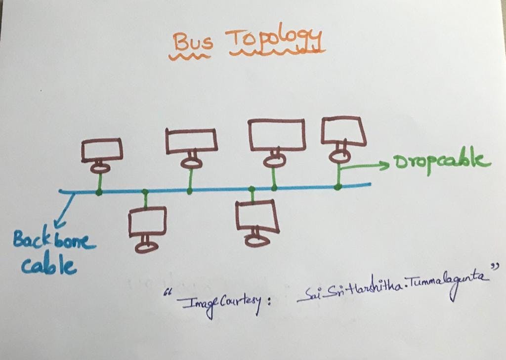
All the devices(computers etc.) are connected through a single cable called "Backbone cable" in Bus topology.
CSMA CD - Carrier Sense Multiple Access - Collision Detection
CSMA CA - Carrier Sense Multiple Access - Collision Avoidance
Key Highlights Of Bus Topology:
Bus topology is a simple network arrangement where all devices share a single communication line, or "bus." It's like a single road where all the data travels. Devices on the network can send or receive data, but the entire network relies on this central communication pathway.
Key Points:
Single Communication Path: All devices are connected to a central cable (bus), and data travels along this cable. It's a shared pathway for communication.
Data Transmission: When a device wants to communicate, it sends data onto the bus. All devices see the data, but only the one it's intended for accepts and processes it.
No Central Hub: Unlike some other topologies, there's no central hub or switch in a bus topology. The cable itself serves as the communication medium.
Simplicity: Bus topology is straightforward and easy to set up. It's like having a single road where everyone can see what's happening.
Advantages:
Simplicity: Easy to install and requires minimal cabling.
Cost-Effective: Requires less cable compared to some other topologies.
Scalability: It's easy to add more devices to the network.
Disadvantages:
Limited Scalability: As more devices are added, the bus can become a bottleneck.
Single Point of Failure: If the central cable (bus) fails, the entire network can go down.
Data Collision: Possibility of data collisions, especially as the number of devices increases.
In a nutshell, bus topology is like having a single road where all the communication happens. It's simple but has limitations in terms of scalability and potential points of failure.
RING TOPOLOGY
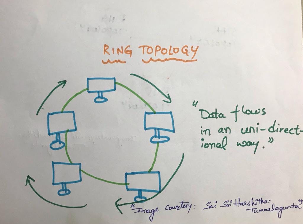
Ring topology is like bus topology but with connected ends.
Data Flows in only one Direction (Uni-Directional)
Data flows in clock wise direction.
Most common access method in ring topology is "token passing"
Token - It is frame that circulates around the network.
Token Passing - It is a Network Access method in which a token is passed from one node to another.
Working of Token Passing - A token moves around the network and it is passed from the computer to computer until it reaches the destination(It checks the address is matched or not once it is matched it reached the destination). The Sender modifies the token by putting the address along with the data. Once the token is received by the destination device then it sends the acknowledgement to the sender.
Ring topology is a network configuration where each device is connected to exactly two other devices, forming a closed loop or circle. Data travels in one direction along the ring until it reaches its destination. Here's a concise overview:
Key Points:
Closed Loop: Devices are connected in a circular or ring-like fashion. The last device is connected to the first, forming a closed loop.
Data Transmission: Data travels in one direction around the ring. Each device reads the data, and if it's not meant for that device, it passes it along to the next one in the ring.
Connectivity: Each device is directly connected to two others, providing a simple and predictable connectivity pattern.
No Central Hub: Unlike some other topologies, there's no central hub or switch. Devices are connected to their immediate neighbors.
Advantages:
Simplicity: Simple to install and understand.
No Collisions: Since data travels in one direction, there is no risk of data collisions.
Disadvantages:
Single Point of Failure: If one device or connection fails, the entire network can be affected.
Limited Scalability: Adding or removing devices can be challenging without disrupting the entire network.
Performance: As the number of devices increases, performance can decrease due to the sequential nature of data transmission.
In a nutshell, ring topology is like a circular communication path where each device is directly connected to two neighbors. It's simple but has challenges in terms of potential points of failure and scalability.
STAR TOPLOOGY
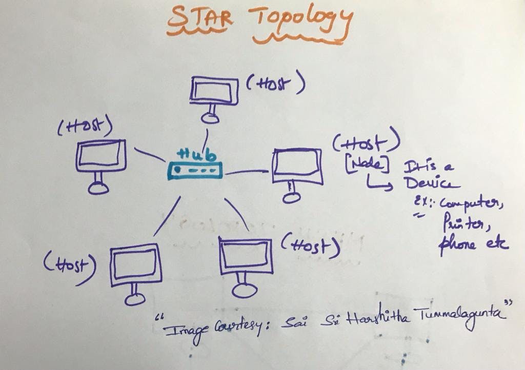
Star topology In this every node is connected to central hub or switch or central computer (Server)
Central device is called "Server".
The peripheral nodes attached to the server are called "Clients"
co-axial cable or RJ-45 are used to connect to the star topology.
Star topology is a network configuration where each device is connected to a central hub or switch. In this setup, all communication passes through the central hub, acting as a focal point for the network. Here's a brief overview:
Key Points:
Central Hub: All devices are connected to a central hub or switch. This central point serves as the main connection and communication mediator for the entire network.
Data Transmission: When one device wants to communicate with another, data travels through the central hub. The hub then directs the data to the specific device it's intended for.
Connectivity: Devices are not directly connected to each other but only to the central hub. If one device wants to communicate with another, the data goes through the hub.
Scalability: Star topology is easily scalable. New devices can be added by connecting them to the central hub without affecting existing connections.
Reliability: If one device fails or a cable is disconnected, it usually doesn't affect the rest of the network. Each connection is independent of the others.
Advantages:
Simplicity: Simple to install and manage.
Centralized Control: Easy to monitor and manage network traffic from the central hub.
Scalability: Adding or removing devices is straightforward.
Disadvantages:
Single Point of Failure: If the central hub fails, the entire network can be affected.
Dependence on Hub: The performance and functionality of the network depend on the central hub.
In a nutshell, star topology is like having a central meeting point where all communication passes through. It's straightforward and scalable, but it has a potential single point of failure in the central hub.
TREE TOPOLOGY
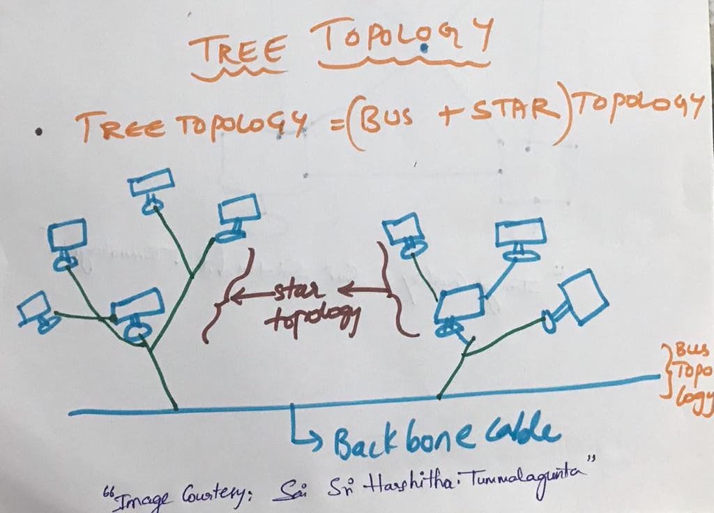
Tree topology, also known as hierarchical topology, is a network configuration that combines characteristics of both bus and star topologies. It forms a tree-like structure with a central "root" node, which branches out into multiple levels. Each branch of the tree can have its own set of sub-branches, and devices are connected at the ends of these branches. Here's a concise overview:
Key Points:
Root Node: There is a central node (root) at the top of the hierarchy from which all other nodes branch out. This root node could be a hub, switch, or server.
Hierarchical Structure: Devices are organized in levels or layers. Each level has a parent-child relationship, forming a hierarchical structure resembling a tree.
Connectivity: Devices are connected to their respective parent nodes. Each node in the hierarchy, except the root, has only one parent.
Data Transmission: Data travels up and down the hierarchy. If a device wants to communicate with another device, the data follows the path from the source to the common root and then down to the destination.
Scalability: Tree topology is scalable. Additional branches or leaves can be added without affecting the rest of the network.
Advantages:
Scalability: Easy to expand by adding branches or leaves.
Hierarchy: Provides a clear and organized structure.
Centralized Control: The root node can have centralized control over the network.
Disadvantages:
Single Point of Failure: If the root node fails, the entire network could be affected.
Complexity: Can become complex as the hierarchy grows.
In a nutshell, tree topology is like a hierarchical tree structure where devices are organized into levels, each level having its own set of branches or leaves. It offers scalability and organization but may have a potential single point of failure in the central root.
MESH TOPOLOGY
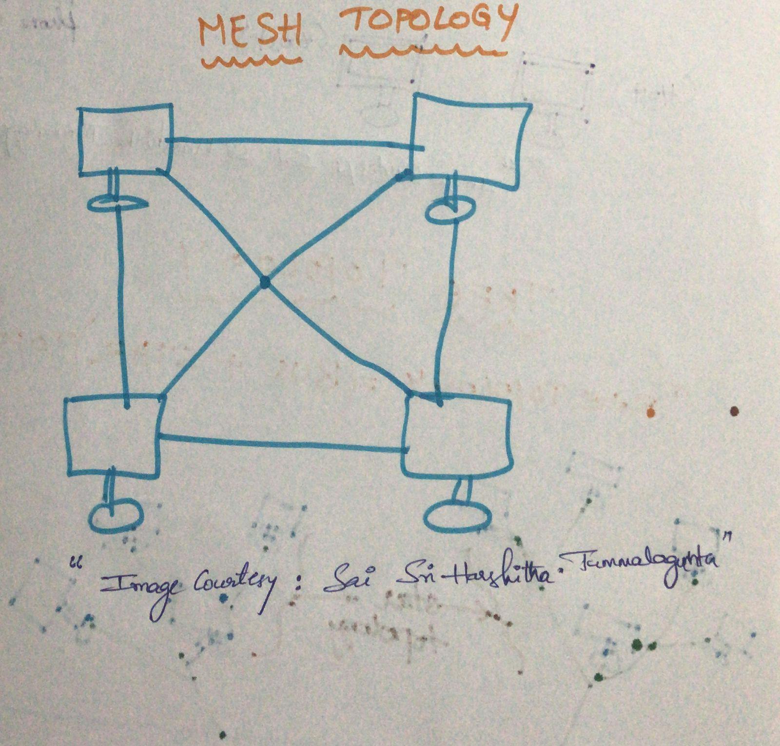
Mesh Topology is an arrangement of Network in which computers are interconnected with each other through series of various redundant connections.
Mesh topology doesn't contain any hub, switch, or any other devices which acts as a central point of communication.
Internet is an example of Mesh Topology.
Mesh topology can be formed using the formula:
Number of cables = (n*n(n-1))/2
where, n = number of nodes that represent a network.
Mesh topology is of 2 types.
Full Mesh - In Full Mesh Topology the each device is connected to all other devices in a network.
Partial Mesh topology - In partial Mesh topology not all the but certain computers are connected to those computers with which they communicate frequently.
6. HYBRID TOPOLOGY
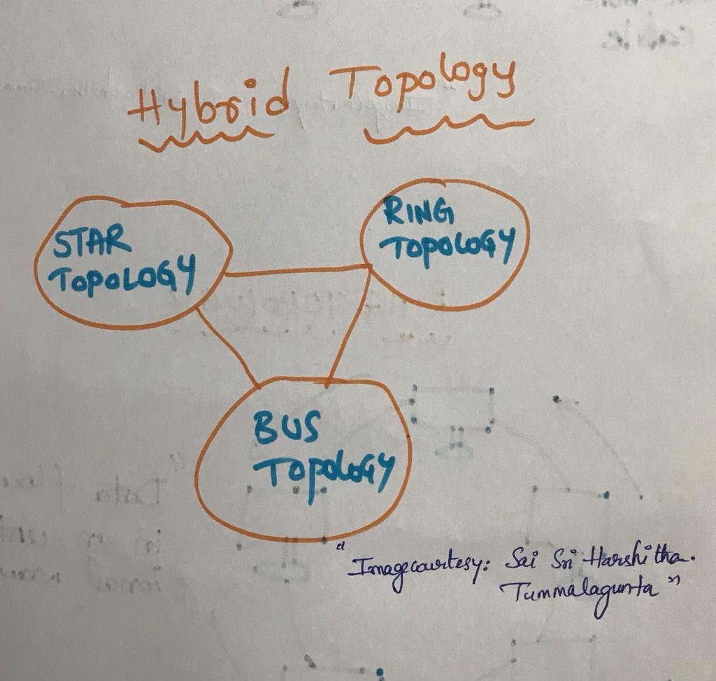
Combination of various(different) topology networks is called hybrid topology.
Mix of same topology networks will not form a hybrid topology. For instance ring topology of one branch should be connected with Bus topology of another branch of a bank to form a hybrid topology.
In crisp a Hybrid topology is a network configuration that combines two or more different types of topologies to form a single network. It's a way of taking the advantages of different topologies while mitigating their individual limitations. Here's a concise overview:
Key Points:
Combination of Topologies: Hybrid topology combines two or more different types of topologies (such as star, bus, ring, or mesh) into a single network.
Different Segments: Different segments of the network can have different topologies, and these segments are connected to create the overall hybrid network.
Flexibility: Hybrid topologies offer flexibility, allowing organizations to design a network that suits their specific needs and requirements.
Example: A common example of hybrid topology is connecting star-configured networks (common in office floors) to form a bus-configured backbone (connecting different floors or departments).
Advantages:
Optimized Performance: Allows for customization to optimize performance and address specific needs.
Scalability: Can be scalable by adding or modifying segments as needed.
Fault Tolerance: Redundancy in design can enhance fault tolerance.
Disadvantages:
Complexity: Designing and managing a hybrid topology can be complex.
Cost: Depending on the specific topologies used, the cost of implementation can vary.
Applications:
Large Organizations: Hybrid topologies are often used in large organizations where different departments or floors have different networking requirements.
Increasing Redundancy: Used in situations where redundancy and fault tolerance are critical.
Optimizing Performance: Employed to optimize network performance based on specific use cases.
In a nutshell, hybrid topology is like creating a customized network by combining different types of topologies. It offers flexibility, allowing organizations to tailor their network configurations to meet specific needs.
TRANSMISSION MODES
It is defined on Layer1 of OSI Model (Physical layer).
Transmission modes, also known as communication modes, describe the direction of data flow between two connected devices in a communication system. There are three main transmission modes: simplex, half-duplex, and full-duplex.
Simplex Mode:
Description: In simplex mode, communication can only occur in one direction. One device is the sender, and the other is the receiver. The sender sends data, and the receiver can only receive; there is no two-way communication.
Example: One-way radio or television broadcasting.
Radio signal is simplex transmission as it transmits the signals to the Listeners but never allows them to transmit back(Talk back).
Half-Duplex Mode:
Description: In half-duplex mode, communication can occur in both directions, but not simultaneously. Devices take turns sending and receiving data. While one device is transmitting, the other can only receive, and vice versa.
Example: Walkie-talkies or traditional push-to-talk systems.
The Military people will use walkie-talkie one person will talk to the distant person and says over and then the other person starts talking back and give commands.
Full-Duplex Mode:
Description: In full-duplex mode, communication can occur in both directions simultaneously. Both devices can send and receive data at the same time, allowing for more efficient and natural conversation.
Example: Telephone conversations, most modern data communication systems.
Our day-to-day conversations.
A
pplications:
Simplex Mode: Commonly used in scenarios where data flows in only one direction, such as television and radio broadcasting.
Half-Duplex Mode: Used in scenarios where devices need to alternate between sending and receiving, such as in two-way radios or traditional walkie-talkies.
Full-Duplex Mode: Widely used in most modern communication systems, including telephones, video conferencing, and data networks.
Considerations:
Data Flow: Simplex allows data flow in one direction, half-duplex alternates, and full-duplex allows simultaneous bidirectional flow.
Efficiency: Full-duplex is more efficient for two-way communication, especially in situations where immediate responses are needed.
Complexity: Simplex and half-duplex modes are simpler to implement than full-duplex, which requires more sophisticated communication protocols.
Understanding transmission modes is essential when designing and implementing communication systems, as it influences the efficiency and capabilities of data transfer between devices.
OSI MODEL
Open System Interconnection Model
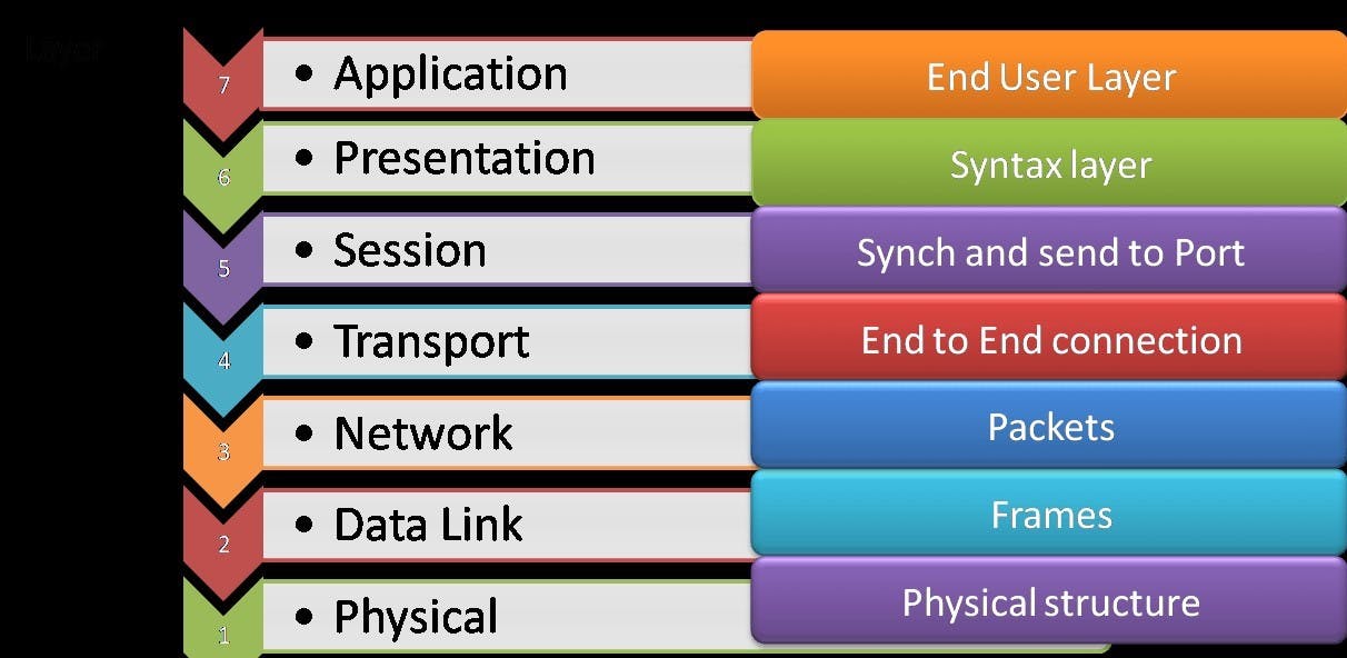
The OSI (Open Systems Interconnection) model is a conceptual framework that standardizes the functions of a telecommunication or computing system into seven abstraction layers. Each layer serves a specific purpose and interacts with the layers above and below it. Here are the seven layers of the OSI model, listed from the bottom (Layer 1) to the top (Layer 7):
Physical Layer (Layer 1):
- Function: Deals with the physical connection between devices. It defines hardware elements such as cables, connectors, and transmission media. It also specifies electrical and mechanical characteristics of the interface.
Data Link Layer (Layer 2):
- Function: Responsible for node-to-node communication. It divides the data into frames and handles error detection and correction at the link level. It ensures the reliable and error-free transmission of data over the physical layer.
Network Layer (Layer 3):
- Function: Focuses on routing and forwarding data packets between devices across different networks. It deals with logical addressing, such as IP addresses, and determines the best path for data to reach its destination.
Transport Layer (Layer 4):
- Function: Manages end-to-end communication and ensures that data is delivered reliably and error-free. It handles flow control, segmentation, and reassembly of data, as well as error recovery.
Session Layer (Layer 5):
- Function: Manages and controls sessions or connections between applications. It establishes, maintains, and terminates connections, providing synchronization and dialogue control between devices.
In short let's understand it in an easy way:
In session layer for suppose consider that you have planned for an event (party) and you hired few Helpers ensuring that each activity runs smoothly, helpers will help you in setting up assisting, cleaning and then closing the party.
similarly Session layer(You) will take help of API (Helpers) in setting up and managing the connections or sessions(party),enabling sending and receiving of data followed by termination of connections or sessions.
NET BIOS is an example of API's which allows "application" on different computers to communicate with each other. Just before a session or connection is established with the server.
Server performs a function called "Authentication" which is process of verifying " WHO YOU ARE?" for this Server uses a "Username" and "Password".
"Authorization" is also done to see if you have permission to access the file or not.
Presentation Layer (Layer 6):
Function: Deals with the syntax and semantics of the information exchanged between systems. It ensures that data is presented in a readable format, handling tasks like data encryption, compression, and character set conversions.
presentation layer receives data from application layer. This data is in the form of characters and numbers.
These characters and numbers are converted into binary format (machine understandable format)
Data compression is really helpful by reducing amount of storage and data transmission can be faster.
Ex: Real time audio and video streaming.
Before transmitting the data is encrypted (converted into another language which is not understandable but done for security purpose) and then it is decrypted back again to the original form.
Application Layer (Layer 7):
- Function: Provides a network interface for end-user applications. It enables communication between software applications and network services. This layer includes protocols for services such as email, file transfer, and remote login.
[APSTNDP] - to remember the layers.
API - Application Programming Interphase
API stands for Application Programming Interface. It is a set of rules and tools that allows different software applications to communicate with each other. APIs define the methods and data formats that applications can use to request and exchange information. Here are some key points about APIs:
Communication Bridge: An API serves as a communication bridge between different software applications. It allows them to interact with each other, share data, and perform specific functions.
Standardized Interface: APIs provide a standardized way for applications to request and receive information, making it easier for developers to integrate different services and functionalities.
Functionality Exposure: APIs expose specific functionalities of a software application to developers, allowing them to use those functionalities without having to understand the internal workings of the application.
Data Exchange: APIs enable the exchange of data between applications. This can include retrieving information from a database, sending data to a remote server, or accessing external services.
Programming Libraries: APIs are often accompanied by programming libraries that include pre-written code to simplify the integration process. Developers can use these libraries to interact with the API without starting from scratch.
HTTP and RESTful APIs: Many APIs use the HTTP protocol for communication, and RESTful APIs (Representational State Transfer) are a common architectural style for designing networked applications. RESTful APIs use standard HTTP methods (GET, POST, PUT, DELETE) for operations.
JSON and XML: APIs often use data formats like JSON (JavaScript Object Notation) or XML (extensible Markup Language) for structuring the data exchanged between applications.
Authentication: APIs often require authentication to ensure that only authorized users or applications can access certain functionalities. This is commonly done using API keys or OAuth tokens.
Web APIs: Many modern APIs are web-based, allowing applications to communicate over the internet. Web APIs are commonly used in web development to integrate services like social media platforms, payment gateways, and more.
Documentation: APIs come with documentation that provides information on how to use the API, including the available endpoints, request formats, and response structures.
APIs play a crucial role in modern software development by enabling the integration of diverse systems and services, fostering collaboration, and promoting the reuse of functionalities across different applications.
Best Example - A food or any other application (app) if it wants to communicate with the Google maps to deliver your order first it will contact the Google Map's API (security layer) and then the API will ask the permission of the Google Map's app and then if it gives the permission then again the API will go back to the food App and tells that the google map gave the permission. That means if the google map gives the permission then the data will flow from Google Map to API and then from API to Food app. If google map declines the permission then the API will throw an error to the food app stating the access denied. Example Sign In option is displayed for already existing user and signup option is used for new user.
DNS - Domain Name System
DNS stands for Domain Name System. Let's break it down in a simple way:
Imagine you want to visit a website, like a cool online game. Instead of remembering a bunch of numbers to get there (which is how computers see websites), you just type in the game's name, like "xyz.com".
Now, here's where DNS comes in—it's like a friendly helper. When you type in "xyz.com," the DNS takes that name and finds the right numbers (IP address) for you. It's like asking your friend where the game is, and your friend tells you the exact location. So, DNS helps your computer find the right place on the internet, making it easier for you to play your favorite games or visit any website you like.
Types of DNS Servers
DNS Recursive Resolver or DNS resolver - It is provided by ISP Internet service provider like Jio, airtel etc*.* It connects "web browser "of our computer to the "DNS Name Servers" (root name server , authoritative name server , Top level domain server)
Root Name Server - Imagine you are in a huge library, and you want to find a specific book. But there's a librarian at the entrance, and this librarian knows where all the sections in the library are.
Now, when you ask this librarian where to find a book, the librarian might not have the book right there, but they tell you which section to go to. This magical librarian is like a root name server on the internet.
For example, let's call this librarian "Mr. A" (like the letter 'A' for one of the root name servers). When you ask Mr. A where to find a website (like a special book), Mr. A doesn't have the website, but he guides you to the right place on the internet, just like telling you which section of the library to check. So, the root name server is like the magical librarian helping you find things on the internet.
Top Level Domain - domains are .com , .net , .in , .edu
.com TLD server -> it has .com extension
.edu TLD serever -> it has .edu extension
.net TLD Server -> it has .net extension
let us assume the internet is like a big playground with lots of different areas for games. Now, the "top-level domain" is like the sign at the entrance of each area, telling you what kind of games you can play there.
For example:
".com" is like the area for companies, so you might find games about shopping or business there.
".org" is like the area for organizations, where you can play games related to groups and causes.
".edu" is like the area for schools, where you can find games about learning.
So, the top-level domain is like the big sign that helps you know what kind of fun you can have in each part of the internet playground.
Authoritative Name Server:
It stores website's IP Address.
let's say the internet as a big city, and you want to know where to find the best ice cream shop. Now, the authoritative name server is like the official expert who knows everything about that ice cream shop.
When you ask this expert where to find the ice cream shop, they give you the exact address. They're not guessing; they have the official, correct information. So, the authoritative name server is like the expert guide who has the real answers about where things are on the internet.
In simpler terms, it's the go-to source that knows exactly where to find specific information on the internet, like the official directory of the coolest places.
It gives the IP Address of a name server so that we can find the device on the network and can it will become easy to send the data packets easily to the destination in a right path.
How a computer loads a website ?
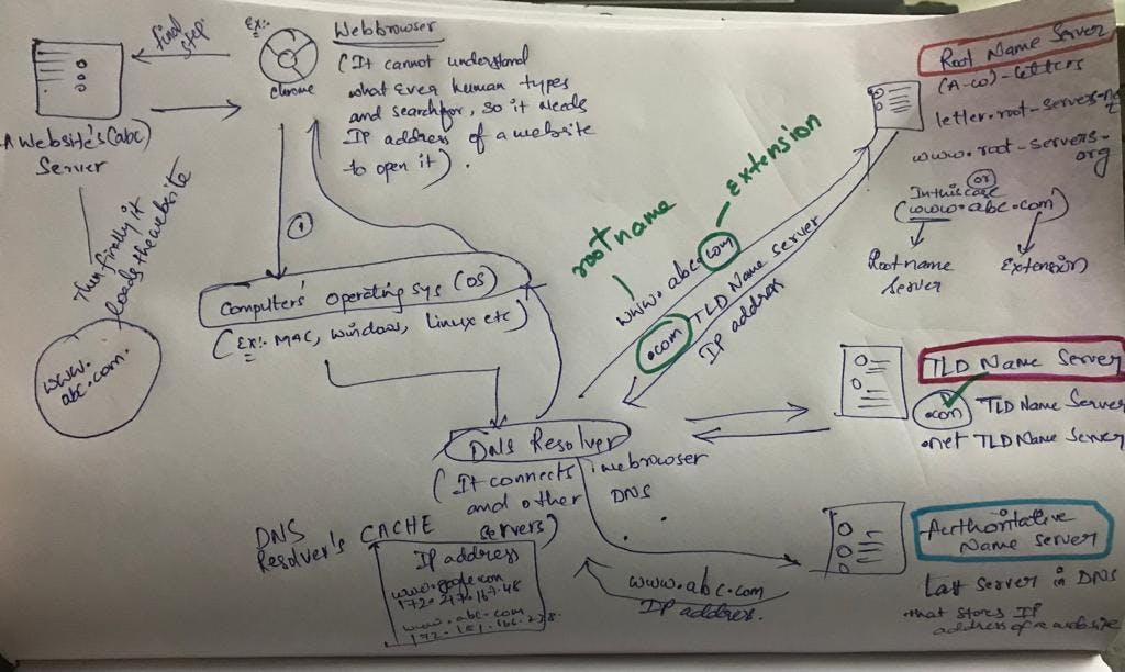
if we type "abc.com" (a website) in the web-browser, then the web-browser(example - chrome) cannot understand the human language so it needs the IP address of the website to redirect you to the website.
Firstly the web-browser goes to the operating system,.
Then the Operating systems are configured to send the query (In this case the IP address of the website) to the DNS Name Server.
Operating system then contacts the DNS resolver and it checks the CACHE whether it has IP address of the requested website.
DNS resolver provides internet service provider(ISP).
If the DNS Resolver does not have the IP address then it will forward the query to other DNS servers like Root Name server , TLD(Top Level Domain), Authoritative Name Server.
When the DNS resolver contacts the Root Name server then it will check the extension (.com or .net) of the website and based on that extension the RNS will provide the IP address of the TLD(Top Level Domain) Server to the DNS Resolver.
DNS resolver then contacts the TLD resolver which provides the "Authoritative Name Server" IP address then the DNS resolver will contact the ANS and it definitely will store the IP address of the requested website.
Then this ANS will give the requested website's IP address to the DNS Resolver and then it will store it in it's CACHE for future use and then this DNS resolver will give it to Computer's Operating System(OS) when requested and then it sends this IP address to the web-browser and further it will send it to the website's sever. It will then load the website.
Since Web browser cannot understand the human language and it needs IP address and we cannot remember all the websites that's the reason we use DNS to get the IP address of the desired website.
ROUTING ALGORITHMSDistance Vector Routing
Distance Vector Routing is a type of routing algorithm used in computer networks to determine the optimal path for data transmission between nodes. The basic idea behind distance vector routing is to maintain a table of distances (or costs) to all reachable destinations and update these distances periodically based on the information received from neighboring nodes.
Here are some key concepts associated with distance vector routing:
Distance Vector Table: Each node in the network maintains a table that records the distance (cost) to every other node in the network. The distance can be measured in terms of metrics like hop count, bandwidth, or latency.
Vector: The term "vector" refers to the direction or path a data packet should take to reach its destination. Each entry in the distance vector table includes the distance and the next-hop information for reaching a specific destination.
Bellman-Ford Algorithm: The Bellman-Ford algorithm is often used to implement distance vector routing. It is an iterative algorithm where each node exchanges its distance vector with its neighbors, and based on this information, each node updates its own distance vector table.
Periodic Updates: Nodes exchange their distance vectors with neighboring nodes at regular intervals, even if there are no changes in the network topology. These periodic updates help ensure that each node has the most up-to-date information about the network.
Convergence: Distance vector routing algorithms are designed to converge, meaning that the routing tables of all nodes eventually stabilize and reach a consistent state. Convergence is crucial for ensuring that the network functions efficiently.
Count-to-Infinity Problem: One challenge with distance vector routing is the "count-to-infinity" problem. If there is a change in the network that causes a link to go down, it may take some time for all nodes to update their tables, and during this time, incorrect information may be propagated, leading to suboptimal routing.
Split Horizon: To address the count-to-infinity problem, the split horizon technique is often used. It prevents a node from advertising a route back to the neighbor from which it was learned.
Examples of distance vector routing protocols include Routing Information Protocol (RIP) and Interior Gateway Routing Protocol (IGRP). However, modern networks often use link-state routing protocols like Open Shortest Path First (OSPF) or Intermediate System to Intermediate System (IS-IS), which offer faster convergence and address some of the limitations associated with distance vector routing.
LINK STATE ALGORITHM
The Link-State Routing Algorithm is a type of routing algorithm used in computer networks to determine the shortest path between nodes within a network. Unlike Distance Vector Routing, which focuses on sharing distance information with neighbors, Link-State Routing focuses on sharing information about the state of links with all nodes in the network. This information includes details about the entire network topology.
Here are the key concepts associated with the Link-State Routing Algorithm:
Link-State Database (LSDB): Each router in the network maintains a database containing the current state of all links in the network. This information includes the state (up or down) of each link and the cost associated with each link.
Link-State Advertisement (LSA): Routers periodically exchange Link-State Advertisements to inform each other about the state of their links. LSAs contain information about the router, the links it is connected to, and the costs associated with those links.
Dijkstra's Shortest Path Algorithm: The Dijkstra's algorithm is commonly used to compute the shortest path from one node to all other nodes in the network based on the information in the LSDB. This algorithm ensures that routers have a complete and consistent view of the network topology.
SPF Tree: The result of the Dijkstra's algorithm is a Shortest Path First (SPF) tree. This tree represents the shortest paths from the source router to all other routers in the network.
Flooding: LSAs are flooded throughout the network to ensure that all routers have an identical view of the network topology. Flooding helps in maintaining a consistent LSDB across all routers.
Hello Packets: Routers use Hello packets to discover and maintain neighbor relationships. Hello packets help routers identify which neighbors are still reachable and which links are still active.
OSPF (Open Shortest Path First): OSPF is a common link-state routing protocol used in many large-scale networks. It is an open standard protocol and supports variable-length subnet masking, making it suitable for modern IP networks.
IS-IS (Intermediate System to Intermediate System): IS-IS is another link-state routing protocol that operates at the OSI layer 2 (datalink layer) and is used in both IP and OSI networks.
Advantages of Link-State Routing Algorithm:
Fast Convergence: Link-state protocols typically converge more quickly than distance vector protocols, as they have a more accurate and up-to-date view of the network topology.
Scalability: Link-state protocols are often more scalable in larger networks due to their efficient use of information about network topology.
Loop Prevention: Link-state protocols inherently prevent loops in the network by using Dijkstra's algorithm to compute loop-free paths.
One challenge with link-state algorithms is the need for more memory and processing power to maintain and compute the LSDB, especially in large networks. However, advancements in hardware have mitigated many of these concerns, and link-state routing protocols are widely used in modern networks.
- Lets understand the concept of Flooding In computer networks: flooding is a communication technique used to broadcast data packets or messages to all nodes in the network. The idea behind flooding is simple: a node sends a message to all of its neighbors, and each receiving node, except the one from which the message was received, forwards the message to all of its neighbors. This process continues until the message reaches all nodes in the network.
Here are key points about flooding in computer networks:
Broadcasting: Flooding is a broadcasting technique, and it is often used when the sender wants to communicate with all nodes in the network without knowing the network's exact topology.
No Prior Knowledge of Topology: Unlike routing algorithms that rely on a pre-established routing table or knowledge of the network's topology, flooding does not require any prior knowledge of the network structure.
Simple Implementation: Flooding is straightforward to implement, as each node simply forwards the received message to all of its neighbors. There is no need for complex routing logic.
Message Duplication: One challenge with flooding is the potential for message duplication. Since each node forwards the message to all neighbors, the same message may traverse the network multiple times, leading to unnecessary bandwidth usage.
Loop Prevention: To avoid infinite loops, nodes typically keep track of the messages they have already forwarded to prevent retransmitting the same message multiple times. This helps prevent the network from being inundated with redundant messages.
Limited Scope: Flooding is not always suitable for all network scenarios. In large networks, the flood of messages can lead to excessive traffic, wasting bandwidth and processing resources.
Example Scenario: In the context of link-state routing protocols, flooding is often used to distribute Link-State Advertisements (LSAs) throughout the network. Each router sends its LSAs to all neighbors, and routers continue to forward LSAs until they reach all routers in the network. This helps maintain a consistent view of the network topology among all routers.
Security Concerns: Flooding can potentially be exploited for malicious purposes, such as launching a distributed denial-of-service (DDoS) attack by flooding the network with a large volume of messages.
While flooding is a simple and effective way to disseminate information across a network, it may not be the most efficient method in all cases. For this reason, more complex routing algorithms, like those used in link-state or distance vector protocols, are often employed in larger and more structured networks. These algorithms aim to optimize the path taken by messages and reduce unnecessary traffic.
FILE TRANSFER PROTOCOL
File Transfer Protocol (FTP), it is a standard network protocol used for the transfer of files from one host to another over a TCP-based network, such as the internet. FTP is a client-server protocol, where a client initiates a connection to a server to request file transfers.
Here are some key points about FTP:
Two Modes of Operation:
Active Mode: The client opens a random port for data transfer, and the server connects to this port. This mode can sometimes pose problems with firewalls.
Passive Mode: The server opens a random port for data transfer, and the client connects to this port. Passive mode is often used to overcome firewall issues.
Authentication:
FTP typically requires a username and password for authentication, though it can be configured for anonymous access.
Secure variations like FTPS (FTP Secure) or SFTP (SSH File Transfer Protocol) provide encryption for secure data transfer.
Commands:
FTP uses a set of commands such as
LISTto see a directory listing,PUTorSTORto upload a file,GETorRETRto download a file, and others.Common commands include changing directories (
CWD), deleting files (DELE), and renaming files (RNFRandRNTO).
Control and Data Connections:
FTP uses two separate connections: a control connection (for sending commands) and a data connection (for actual file transfers).
The control connection is used to manage the session, while the data connection is established as needed for file transfers.
Security Considerations:
Standard FTP sends data in plain text, which can pose security risks. Secure versions like FTPS and SFTP use encryption to address this concern.
FTPS adds a secure layer over the existing FTP, while SFTP is a separate, secure protocol.
Port Numbers:
FTP uses well-known port numbers: 21 for the control connection and 20 for the data connection in active mode.
In passive mode, the server opens a random high-numbered port for the data connection.
Use Cases:
- FTP is commonly used for transferring files on the internet, managing website content, and uploading or downloading files to and from servers.
It's worth noting that while FTP has been widely used, it may lack some of the security features provided by more modern protocols. In scenarios where security is a significant concern, protocols like SFTP or FTPS are often preferred due to their encryption capabilities.
TELNET
TELNET, short for "Terminal Network," is a network protocol that allows a user to interact with remote computers or devices over a TCP/IP network. It was widely used in the early days of the internet and is still available on many systems, although its use has diminished in favor of more secure alternatives due to its lack of encryption. TELNET provides a virtual terminal connection, allowing a user to log in to a remote system and execute commands as if they were directly connected to the system.
Here are some key points about TELNET:
Client-Server Architecture: TELNET operates on a client-server model. The TELNET client is the application or device used to initiate a connection, while the TELNET server runs on the remote system, providing the terminal interface.
Port Number: The default port number for TELNET is 23. When a user connects to a TELNET server, the communication takes place over this port.
Text-Based Communication: TELNET transfers data in plain text, including login credentials and commands. As a result, it lacks encryption, making it vulnerable to eavesdropping. This lack of security is a significant drawback, and TELNET is often avoided in favor of more secure alternatives like SSH (Secure Shell).
Commands and Control Sequences: TELNET allows users to interact with remote systems by sending commands and receiving responses. Control sequences, such as those for cursor movement and text formatting, can also be transmitted.
Authentication: TELNET supports basic authentication mechanisms, including username and password. However, because it lacks encryption, login credentials can be intercepted by malicious actors if the communication is not secured through other means, such as a Virtual Private Network (VPN).
Obsolete and Insecure: Due to its lack of security features, TELNET is considered obsolete for most applications where data confidentiality is important. Secure Shell (SSH) has largely replaced TELNET in secure communication scenarios.
Use Cases: TELNET was historically used for various purposes, including remote administration, debugging, and accessing text-based applications on remote servers. However, its use has declined in favor of more secure and modern protocols.
While TELNET is still supported by some systems, its use is strongly discouraged over untrusted networks or the public internet. Secure alternatives like SSH provide encrypted communication, ensuring the confidentiality of data transmitted between the client and server. If remote terminal access is required, SSH is generally recommended over TELNET for security reasons.
- TELNET is not that secure so better to use SSH (Secure Shell) with TELNET.
SMTP - Simple Mail Transfer Protocol
Simple Mail Transfer Protocol (SMTP) is a protocol used for sending and receiving email in a network. It is a text-based protocol that works in conjunction with other email protocols like POP3 (Post Office Protocol) or IMAP (Internet Message Access Protocol), which are used for retrieving emails.
Here are key points about SMTP:
Communication Model:
SMTP follows a client-server communication model.
The SMTP client initiates a connection with the SMTP server to send an email.
Port Number:
SMTP uses port 25 by default for communication between mail servers.
For secure communication, SMTP over TLS/SSL (SMTPS) can use port 587.
Text-Based Protocol:
SMTP commands and responses are text-based. Commands are sent by the client, and the server responds accordingly.
Examples of SMTP commands include EHLO (extended hello), MAIL FROM (specifying the sender's address), RCPT TO (specifying the recipient's address), and DATA (to start the message content).
Message Format:
SMTP is responsible for sending the email message from the sender's mail server to the recipient's mail server.
It transfers the email content, including the headers and body, but does not deal with storing or retrieving emails.
Relaying:
- SMTP is designed to relay messages between mail servers. When you send an email, your email client communicates with your outgoing mail server, which then uses SMTP to send the message to the recipient's mail server.
SMTP Commands:
EHLO: Initiates the session and identifies the client to the server.
MAIL FROM: Specifies the sender's email address.
RCPT TO: Specifies the recipient's email address.
DATA: Indicates the start of the message content.
QUIT: Ends the session.
Authentication:
- SMTP servers may require authentication to prevent unauthorized use. Common authentication methods include LOGIN, PLAIN, and CRAM-MD5.
Security Considerations:
- SMTP does not provide encryption for message content. To secure email communication, it is recommended to use additional protocols like SMTPS or STARTTLS, which provide a secure layer.
SMTPS and STARTTLS:
SMTPS (SMTP Secure) is SMTP over SSL/TLS on a separate port (e.g., port 465).
STARTTLS is a command used to upgrade a plain text connection to an encrypted connection during the SMTP session.
Use Cases:
SMTP is widely used for sending emails from one mail server to another.
It is used by email clients (such as Outlook, Thunderbird) to send emails through the user's outgoing mail server.
SMTP is a fundamental protocol for email communication, and it works in conjunction with other protocols like POP3 or IMAP, which are used for retrieving emails from a mail server. As with any text-based protocol, security concerns have led to the development of secure variants like SMTPS and the use of STARTTLS for encrypted communication.
TCP - TRANSMISSION CONTROL PROTOCOL
TCP, or Transmission Control Protocol, is one of the core protocols of the Internet Protocol (IP) suite. Together with IP (Internet Protocol), it forms the basis for the Internet and most networks. TCP is a connection-oriented protocol that provides reliable, stream-oriented communication between two devices over an IP network.
Here are key points about TCP:
Connection-Oriented:
TCP is connection-oriented, meaning that a connection is established between two devices before data is exchanged.
It ensures reliable and ordered delivery of data between the sender and receiver.
Three-Way Handshake:
The process of establishing a connection in TCP involves a three-way handshake: SYN (synchronize), SYN-ACK (synchronize acknowledgment), and ACK (acknowledge).
This handshake helps ensure that both the sender and receiver are ready for data transfer.
Reliability:
TCP ensures reliable data delivery by using mechanisms like acknowledgment and retransmission.
If a segment is not acknowledged, it is retransmitted.
Flow Control:
TCP employs flow control mechanisms to prevent a fast sender from overwhelming a slow receiver.
It uses a sliding window mechanism to control the amount of unacknowledged data.
Ordered Data Delivery:
- TCP guarantees that data is delivered to the receiver in the same order it was sent by the sender.
Full-Duplex Communication:
- TCP supports full-duplex communication, allowing data to be transmitted bidirectionally simultaneously.
Connection Termination:
- TCP connections are terminated using a four-way handshake to ensure that both sides are ready to close the connection.
Ports:
TCP uses port numbers to identify specific applications or services on devices.
The combination of an IP address and a port number uniquely identifies a process on a given device.
Segmentation and Reassembly:
Data is transmitted in TCP in the form of segments, which are units of data with headers.
Large messages are broken into smaller segments for transmission and are reassembled at the destination.
Stateful Protocol:
TCP is a stateful protocol, meaning that it keeps track of the state of the connection.
This state information is crucial for managing the flow of data, acknowledging received segments, and handling connection termination.
Acknowledgments:
TCP uses acknowledgments to confirm the receipt of data segments.
If an acknowledgment is not received within a specified time, the sender retransmits the data segment.
Error Detection:
TCP includes error detection mechanisms to identify corrupted or lost data.
If errors are detected, the receiver requests retransmission of the corrupted segments.
TCP is widely used for various applications, including web browsing, file transfer (e.g., FTP), email (e.g., SMTP), and many other protocols that require reliable and ordered data delivery. It plays a critical role in ensuring the integrity and reliability of data transmission across the Internet and other networks.
UDP
UDP, or User Datagram Protocol, is one of the core protocols in the Internet Protocol (IP) suite. It is a connectionless and lightweight transport layer protocol that provides a simple mechanism for exchanging datagrams (packets) between devices on a network. UDP is often used in scenarios where low latency and simplicity are more critical than reliability and error recovery.
Here are key points about UDP:
Connectionless Communication:
UDP is connectionless, meaning that it does not establish a dedicated connection before transmitting data.
Each UDP datagram is treated independently, and there is no concept of a connection setup or teardown.
Unreliable Delivery:
UDP does not provide guaranteed delivery of data, and there is no mechanism for retransmitting lost or corrupted packets.
It is considered an unreliable protocol compared to TCP (Transmission Control Protocol).
Low Overhead:
UDP has lower overhead than TCP, making it more lightweight in terms of processing and bandwidth usage.
It lacks features such as flow control, error recovery, and sequencing found in TCP.
No Congestion Control:
UDP does not implement congestion control mechanisms, which can result in the transmission of data even in congested network conditions.
This lack of congestion control can be both an advantage and a disadvantage, depending on the application requirements.
Packet Format:
UDP datagrams consist of a simple header with fields for source and destination port numbers, length, and a checksum for error detection.
The minimal header contributes to the protocol's efficiency.
Ports:
UDP uses port numbers to distinguish different services or applications on a device.
The combination of an IP address and a UDP port number identifies a specific process or service.
Broadcast and Multicast:
- UDP supports broadcast and multicast communication, allowing a single packet to be sent to multiple recipients.
Real-Time Applications:
- UDP is commonly used in real-time applications where low latency is critical, such as streaming media, voice over IP (VoIP), online gaming, and live broadcasts.
DNS (Domain Name System):
UDP is often used in DNS queries and responses.
DNS uses UDP for its simplicity and lower overhead, reserving TCP for larger data transfers or situations where reliability is essential.
No Handshaking:
UDP does not perform a three-way handshake like TCP for connection establishment.
This lack of handshaking contributes to lower latency but comes at the cost of reliability.
Examples of Applications:
Video streaming and VoIP (Voice over Internet Protocol)
Online gaming and real-time communication applications
DNS queries
SNMP (Simple Network Management Protocol) for network management
While UDP lacks some of the reliability features provided by TCP, its simplicity and low overhead make it suitable for applications where timely delivery of data is more critical than ensuring every packet arrives. It is particularly well-suited for real-time and multimedia applications where a slight loss of data is acceptable, but low latency is essential.
IPV4
IPv4, or Internet Protocol version 4, is one of the core protocols of the Internet Protocol suite. It is the fourth version of the Internet Protocol and has been the dominant protocol used for the majority of the Internet's history. IPv4 is responsible for the addressing and routing of packets of data so that they can travel across networks and arrive at the correct destination.
Here are key points about IPv4:
Address Format:
IPv4 addresses are 32-bit numerical labels written in dotted-decimal format, such as 192.168.1.1.
The 32 bits are typically divided into four octets, each represented by a decimal number.
Address Space:
IPv4 provides a total of 2^32 (approximately 4.3 billion) unique addresses.
The increasing demand for Internet-connected devices has led to address exhaustion issues.
Subnetting:
IPv4 addresses can be subdivided into smaller networks known as subnets.
Subnetting allows organizations to efficiently allocate and manage IP addresses within their networks.
Classes:
IPv4 originally used a class-based addressing scheme with Classes A, B, and C, each designed for different-sized networks.
Classless Inter-Domain Routing (CIDR) introduced a more flexible addressing scheme that allows for variable-length subnetting.
Private Addresses:
- Reserved address ranges, known as private addresses, are used for internal networks. Common private address ranges include 10.0.0.0 to 10.255.255.255, 172.16.0.0 to 172.31.255.255, and 192.168.0.0 to 192.168.255.255.
Protocols:
- IPv4 is used in conjunction with higher-layer protocols, such as Transmission Control Protocol (TCP) for reliable communication and User Datagram Protocol (UDP) for connectionless communication.
Packet Header:
IPv4 packets consist of a header and payload.
The header contains information such as source and destination IP addresses, protocol information, time-to-live (TTL), and header checksum.
TTL (Time-to-Live):
TTL is a field in the IPv4 header that specifies the maximum number of hops (routers) a packet can traverse before being discarded.
TTL helps prevent packets from circulating indefinitely in the case of routing loops.
Address Resolution:
- Address resolution is accomplished through the Address Resolution Protocol (ARP), which maps IP addresses to physical MAC addresses on a local network.
Transition to IPv6:
Due to the limited address space of IPv4 and the growth of the Internet, IPv6 (Internet Protocol version 6) was introduced to provide a vastly expanded address space.
IPv6 adoption is ongoing, and efforts are made to transition from IPv4 to IPv6.
IPv4 continues to be widely used, but the adoption of IPv6 is becoming increasingly important to accommodate the growing number of devices connected to the Internet. IPv6 provides a much larger address space and includes enhancements to address some limitations of IPv4. The coexistence and eventual transition from IPv4 to IPv6 are key considerations in the ongoing evolution of the Internet.
IPV6
IPv6, or Internet Protocol version 6, is the most recent version of the Internet Protocol, designed to replace the older IPv4 protocol. IPv6 was introduced to address the limitations of IPv4, particularly the exhaustion of available IP addresses due to the growing number of devices connected to the Internet. IPv6 provides a significantly larger address space, improved security features, and other enhancements.
Here are key points about IPv6:
Address Format:
IPv6 addresses are 128-bit numerical labels written in hexadecimal format, separated by colons, such as 2001:0db8:85a3:0000:0000:8a2e:0370:7334.
The 128 bits allow for a vastly expanded address space compared to IPv4.
Address Space:
IPv6 provides an immense address space, with 2^128 unique addresses.
The larger address space is designed to accommodate the increasing number of devices connected to the Internet.
Simplified Header:
The IPv6 header is simplified compared to IPv4, with certain fields removed or made optional.
IPv6 uses extension headers to add optional features, reducing the complexity of the base header.
Autoconfiguration:
- IPv6 includes built-in support for Stateless Address Autoconfiguration (SLAAC), allowing devices to automatically configure their IPv6 addresses without the need for DHCP (Dynamic Host Configuration Protocol).
Multicast and Anycast:
IPv6 has improved support for multicast and anycast communication, making it more efficient for certain network operations.
Anycast allows multiple devices to share the same IPv6 address, with the packet being routed to the nearest (topologically) device using that address.
Security Enhancements:
IPv6 includes IPsec (Internet Protocol Security) as a mandatory part of the protocol suite.
IPsec provides authentication and encryption at the IP layer, enhancing the security of communications.
Transition Mechanisms:
Various transition mechanisms have been developed to facilitate the coexistence of IPv4 and IPv6 during the transition period.
Dual-stack deployment allows devices and networks to support both IPv4 and IPv6 simultaneously.
IPv6 over IPv4 Tunnels:
IPv6 packets can be encapsulated within IPv4 packets to traverse IPv4 networks using tunneling mechanisms.
This allows IPv6-enabled devices to communicate over IPv4 infrastructure.
Importance of IPv6 Adoption:
The exhaustion of available IPv4 addresses has driven the need for widespread IPv6 adoption.
Many Internet service providers (ISPs) and organizations are actively working to enable IPv6 support in their networks.
Global Unicast Addresses:
IPv6 uses global unicast addresses for unique identification on the global Internet.
These addresses are assigned based on regional and global allocations.
IPv6 adoption is crucial for the continued growth of the Internet, as it provides the necessary address space and features to support the increasing number of devices connected worldwide. While IPv4 is still widely used, the ongoing transition to IPv6 is a key focus to ensure the long-term sustainability of the Internet.
ADDRESS RESOLUTION PROTOCOL
ARP, or Address Resolution Protocol, is a network protocol used to map a 32-bit IPv4 address to the physical hardware address (MAC address) in a local area network (LAN). It is an essential part of the TCP/IP protocol suite and is primarily used to discover the MAC address associated with a given IP address on a local network.
Here are key points about ARP:
IP-to-MAC Address Resolution:
- ARP is used to resolve the layer-3 (IP) address of a device to its corresponding layer-2 (MAC) address within a local network.
ARP Table (Cache):
Each device on a network maintains an ARP table or ARP cache, which is a mapping between IP addresses and corresponding MAC addresses.
The ARP table helps devices avoid repeatedly sending ARP requests for the same IP address.
ARP Request and Reply:
When a device needs to communicate with another device on the same local network and it does not have the corresponding MAC address, it sends an ARP request broadcast.
The ARP request contains the target IP address, and all devices on the network receive the request.
The device that has the matching IP address responds with its MAC address in an ARP reply.
ARP Operation:
ARP operates at the Link Layer (Layer 2) of the OSI model.
ARP requests and replies are encapsulated within Ethernet frames in Ethernet-based networks.
Gratuitous ARP:
Gratuitous ARP is an ARP request or reply that is sent by a device without a previous ARP request.
It is often used by a device to announce its presence or to update the ARP cache of other devices.
ARP Spoofing/Cache Poisoning:
ARP spoofing involves sending false ARP messages to associate a different MAC address with an IP address.
This malicious activity can be used for man-in-the-middle attacks, intercepting traffic, and compromising network security.
ARP Timeout:
ARP cache entries have a finite lifetime, and devices periodically time out and remove stale entries.
When a device needs to communicate again with a device whose ARP cache entry has expired, it will send a new ARP request.
Proxy ARP:
- In some network configurations, a router can respond to ARP requests on behalf of hosts in a different subnet. This is known as proxy ARP.
ARP and IPv6:
- While ARP is primarily associated with IPv4, IPv6 uses a different protocol called NDP (Neighbor Discovery Protocol) for address resolution.
ARP is a fundamental protocol for local network communication, allowing devices to discover each other's MAC addresses and facilitating the forwarding of data within the same subnet. It plays a crucial role in ensuring that devices can communicate efficiently at the link layer of the network stack.
FIREWALL
A firewall is a network security device or software that monitors and controls incoming and outgoing network traffic based on predetermined security rules. It acts as a barrier between a trusted internal network and untrusted external networks, such as the internet, to prevent unauthorized access, data breaches, and other cyber threats. Firewalls can be implemented in both hardware and software forms and are a fundamental component of a comprehensive network security strategy.
Here are key points about firewalls:
Packet Filtering:
Firewalls inspect data packets moving in and out of a network based on predetermined rules.
Packets that meet the criteria defined in the rules are allowed, while those that violate the rules are blocked.
Stateful Inspection:
Stateful inspection (dynamic packet filtering) monitors the state of active connections and makes decisions based on the context of the traffic.
It keeps track of the state of active connections to determine whether incoming packets are part of an established connection.
Proxy Filtering:
Proxy servers act as intermediaries between clients and servers, and they can be used in firewall setups to filter and control traffic.
The firewall acts as a proxy for user requests, inspecting and filtering the traffic before forwarding it to the destination.
Network Address Translation (NAT):
Firewalls often include NAT functionality, which allows multiple devices on a local network to share a single public IP address.
NAT helps conceal the internal network structure and provides an additional layer of security.
Application Layer Filtering:
Firewalls can filter traffic at the application layer (Layer 7 of the OSI model) based on specific applications or services.
This allows organizations to control access to specific applications or block potentially malicious content.
Intrusion Detection and Prevention Systems (IDPS):
Some firewalls incorporate intrusion detection and prevention capabilities to identify and block known and unknown threats.
These systems use signature-based and behavioral analysis techniques to detect and mitigate attacks.
Virtual Private Network (VPN) Support:
Firewalls often include VPN support for secure remote access to a network.
VPNs use encryption to secure communication over untrusted networks, such as the internet.
Logging and Reporting:
Firewalls generate logs that record information about network traffic, rule violations, and security events.
Logging and reporting features are essential for monitoring and analyzing network activity.
Default Deny Policy:
Firewalls typically operate on a default-deny policy, meaning that all traffic is denied unless explicitly allowed by defined rules.
Administrators configure rules to permit specific types of traffic.
Hardware and Software Firewalls:
Hardware firewalls are standalone devices positioned between a network and its connection to the internet.
Software firewalls are installed on individual computers or servers to provide protection at the operating system level.
Next-Generation Firewalls (NGFW):
NGFWs integrate traditional firewall functionality with additional features such as deep packet inspection, application awareness, and advanced threat protection.
They provide a more holistic approach to network security.
Cloud Firewalls:
Cloud-based firewalls are designed to protect virtualized environments and cloud services.
They operate in the cloud to secure data and applications hosted in cloud platforms.
Firewalls are crucial for safeguarding networks from various cyber threats, including unauthorized access, malware, and other malicious activities. They are a foundational element of network security, working alongside other security measures such as intrusion detection systems, antivirus software, and secure access controls.
HTTP STATUS CODE
HTTP status codes are three-digit numbers returned by web servers to indicate the status of a client's request made to the server. These status codes are part of the HTTP (Hypertext Transfer Protocol) standard and are grouped into five classes based on the first digit of the code. Each class signifies a different type of response. Here's a breakdown:
1xx (Informational):
These are informational status codes, indicating that the request was received, continuing process, or that the server is awaiting a request from the client.
Example: 100 Continue, 101 Switching Protocols.
2xx (Successful):
These codes indicate that the request was successfully received, understood, and accepted.
Example: 200 OK (Standard response for successful HTTP requests), 201 Created (Request has been fulfilled; new resource created).
3xx (Redirection):
These codes indicate that further action is needed to complete the request, such as following a redirect.
Example: 301 Moved Permanently (Requested resource has been permanently moved to a new location), 302 Found (Requested resource temporarily resides under a different URI).
4xx (Client Error):
These codes indicate that the client seems to have made an error, and the server won't fulfill the request.
Example: 400 Bad Request (The request cannot be fulfilled due to bad syntax), 403 Forbidden (The server understood the request, but it refuses to authorize it).
5xx (Server Error):
These codes indicate that the server failed to fulfill a valid request.
Example: 500 Internal Server Error (A generic error message returned when an unexpected condition was encountered), 503 Service Unavailable (The server is not ready to handle the request).
These status codes play a crucial role in communication between clients (typically web browsers) and servers. They provide information about the success or failure of a request and guide the client on how to proceed. Developers and system administrators often use these status codes for troubleshooting and improving the performance and reliability of web applications.
Most of the topics related to computer Networks I have made it into a easy notes so that you can go through your desired topic and get the most of it.
Thanks for reading, Have a great day !!!
Blog writer - "Sai Sri Harshitha Tummalagunta"